NURBS Mesh (01-nurbs-mesh)
This example shows how to use full-featured NURBS to define curved boundary edges. Recall that simplified format is available for circular arcs, as was shown in example 03-poisson.
General description of NURBS
Every NURBS curve is defined by its degree, control points with weights and the
knot vector. The degree  is a positive integer, usually 1, 2, 3 or 5. Lines
and polylines are of degree 1, circles have degree 2 and free-form curves are
of degree 3 or 5. The control points
is a positive integer, usually 1, 2, 3 or 5. Lines
and polylines are of degree 1, circles have degree 2 and free-form curves are
of degree 3 or 5. The control points  ,
,  , are the main tool for changing the
shape of the curve. A curve of degree must have at least
, are the main tool for changing the
shape of the curve. A curve of degree must have at least  control
points. In Hermes, the endpoints of the edge are always assumed to be the
first and last control points and therefore only the inner control points are
listed in the mesh file. There is a weight
control
points. In Hermes, the endpoints of the edge are always assumed to be the
first and last control points and therefore only the inner control points are
listed in the mesh file. There is a weight  for every control point,
that influences the shape of the curve in its vicinity. If
for every control point,
that influences the shape of the curve in its vicinity. If  then
has no effect on the shape. As
then
has no effect on the shape. As  increases, the curve is pulled
towards .
increases, the curve is pulled
towards .
The knot vector is a sequence of  values that determines how much and
where the control points influence the shape. The relation
values that determines how much and
where the control points influence the shape. The relation  must
hold. The sequence is nondecreasing,
must
hold. The sequence is nondecreasing,  , and divides the whole
interval
, and divides the whole
interval ![[0,1]](../../../_images/math/41feab2dbf4792693ef8d40a86a38523f14cba84.png) into smaller intervals which determine the area of influence
of the control points. Since the curve has to start and end at the edge
vertices, the knot vector in Hermes always starts with zeros and ends
with ones. Only the inner knots are listed in the above definition of the
variable curves, where
into smaller intervals which determine the area of influence
of the control points. Since the curve has to start and end at the edge
vertices, the knot vector in Hermes always starts with zeros and ends
with ones. Only the inner knots are listed in the above definition of the
variable curves, where  is a simple list of real values.
Sample mesh file
The comments in the mesh file “domain-4.mesh” are self-explanatory:
a = 1.0
ma = -1.0

#b = sqrt(2)/2
b = 0.70710678118654757

ab = 0.70710678118654757

a1 = 0.25
a2 = 0.5
a3 = 0.75

c1 = -1.5
c2 = -0.5

b1 = -1.5
b2 = -2

d1 = 0.2
d2 = 0.7

vertices = [
  [ 0,  ma],    # vertex 0
  [ a, ma ],    # vertex 1
  [ ma, 0 ],    # vertex 2
  [ 0, 0 ],     # vertex 3
  [ a, 0 ],     # vertex 4
  [ ma, a ],    # vertex 5
  [ 0, a ],     # vertex 6
  [ ab, ab ]  # vertex 7
]

elements = [
  [ 0, 1, 4, 3, "1"  ],   # quad 0
  [ 3, 4, 7,    "1"  ],   # tri 1
  [ 3, 7, 6,    "2" ],  # tri 2
  [ 2, 3, 6, 5, "2" ]   # quad 3
]

boundaries = [
  [ 0, 1, "Bottom Layer" ],
  [ 1, 4, "Outer Layer" ],
  [ 3, 0, "Inner Layer" ],
  [ 4, 7, "Outer Layer" ],
  [ 7, 6, "Outer Layer" ],
  [ 2, 3, "Inner Layer" ],
  [ 6, 5, "Outer Layer" ],
  [ 5, 2, "Left Boundary" ]
]

degree_1 = 4

inner_points_1 = [
  [ a1, c1, 1.0 ],
  [ a2, c2, 1.0 ],
  [ a3, c1, 1.0 ]
]

knots 1 = [
  0, 0, 0, 1, 1, 1
]

degree_2 = 3

inner_points_2 = [
  [ b1, d1, 0.5],
  [ b2, d2, 1.0]
]

knots_2 = [
  0, 0, 0, 1, 1, 1
]

angle_1 = 45

curves = [
  [ 4, 7, angle_1 ],  # circular arc with central angle of 45 degrees
  [ 7, 6, 45 ],       # circular arc with central angle of 45 degrees
  [ 0, 1, degree_1, inner_points_1, knots 1],
  [ 2, 5, degree_2, inner_points_2, knots_2]
]
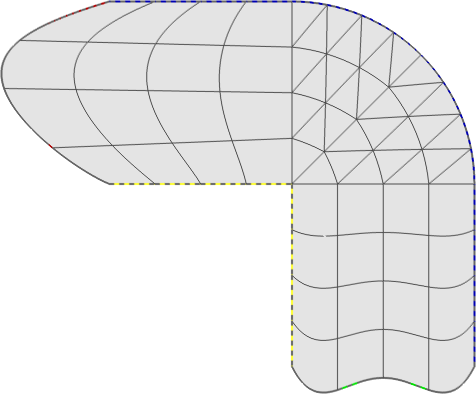
Resulting mesh image