Finite Element Mesh (01-mesh)
Every finite element computation starts with partitioning the domain into a finite element mesh. Hermes admits (possibly curvilinear) triangles and quadrilaterals that can be arbitrarily combined. This is useful since triangular elements are best for approximating isotropic solutions (solutions that have similar behavior in all spatial directions) while quads are much better for approximating anisotropies such as boundary layers.
In contrast to traditional non-adaptive low-order finite element codes that require fine initial meshes, in Hermes it often suffices to create a rather coarse initial mesh by hand, apply a few steps of a-priori mesh refinement, and then let automatic adaptivity take care of the rest. Of course, Hermes can also read fine meshes created automatically by external mesh generation packages.
Hermes2D native mesh format
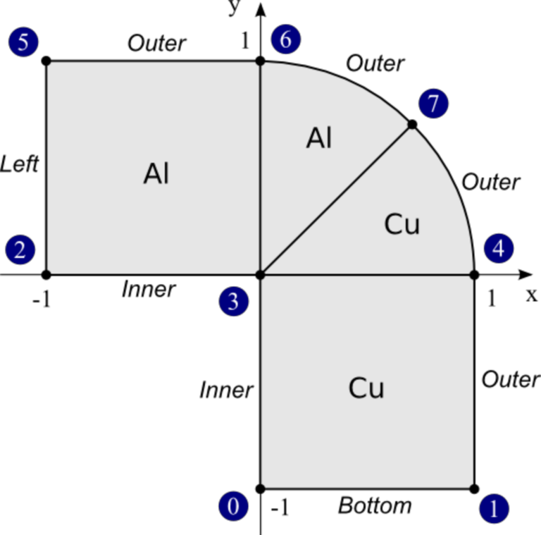
Consider a simple L-shaped domain consisting of two materials (Copper and Aluminum), that is initially split into four elements - two quadrilaterals and two curvilinear triangles:
The corresponding native Hermes mesh file looks as follows:
a = 1.0
ma = -1.0
b = 0.70710678118654757
ab = 0.70710678118654757

vertices = [
  [ 0,  ma],    # vertex 0
  [ a, ma ],    # vertex 1
  [ ma, 0 ],    # vertex 2
  [ 0, 0 ],     # vertex 3
  [ a, 0 ],     # vertex 4
  [ ma, a ],    # vertex 5
  [ 0, a ],     # vertex 6
  [ ab, ab ]    # vertex 7
]

elements = [
  [ 0, 1, 4, 3, "Copper"  ],   # quad 0
  [ 3, 4, 7,    "Copper"  ],   # tri 1
  [ 3, 7, 6,    "Aluminum" ],  # tri 2
  [ 2, 3, 6, 5, "Aluminum" ]   # quad 3
]

boundaries = [
  [ 0, 1, "Bottom" ],
  [ 1, 4, "Outer" ],
  [ 3, 0, "Inner" ],
  [ 4, 7, "Outer" ],
  [ 7, 6, "Outer" ],
  [ 2, 3, "Inner" ],
  [ 6, 5, "Outer" ],
  [ 5, 2, "Left" ]
]

curves = [
  [ 4, 7, 45 ],  # circular arc with central angle of 45 degrees
  [ 7, 6, 45 ]   # circular arc with central angle of 45 degrees
]
Variables
Hermes mesh file consists of variables. Each variable can hold a real number, list of real numbers, or list of lists. The following are all valid definitions:
# comments (starting with a hash)
var = 5.0                                # number
list = [ 1, 2, 3, 4, var ]               # list
pairs = [ [1, 2], [1, var], [0, list] ]  # list of lists
Vertices
The variable vertices defines the coordinates of all mesh vertices. The position of a vertex in this list serves as an index for defining elements. These indices start at zero.
Elements
The variable elements defines all elements in the mesh via zero-based indices of their vertices in counter-clockwise order, plus an extra string (or nonnegative integer) denoting the element’s material marker. Material markers make it possible to use different weak forms in subdomains. This is useful when the domain consists of multiple materials, but it is also possible to assign completely different physical processes to subdomains in this way. The user can access the element and boundary markers from inside of weak forms. Integer markers do not have to be in apostrophes.
Boundaries
The last mandatory variable, boundaries, defines boundary markers for all boundary edges. An edge is identified by a triplet: two vertex indices and a marker (either string or a positive integer).
Note: boundary markers cannot be zeros or negative integers. Negative integers can be used to identify internal edges for the purpose of making them curved. However, it is recommended not to overuse curved edges since this increases the cost of numerical integration, and thus curved elements add to computing time.
For historical reasons, some (mostly older) Hermes examples still use integer markers, but the trend is to use strings that make the mesh files easier to read. String markers are converted to integers by Hermes internally.
Curves (Circular arcs and general NURBS)
The mesh file can also include the variable curves that lists all curved edges. Each curved edge is described by one Non-Uniform Rational B-Spline (NURBS) defined via its degree, control points and knot vector. For an explanation of NURBS see, e.g., the Wikipedia NURBS page
The most common type of curved boundary is a circular arc which is defined via two vertex indices and central angle. For the treatment of full-featured NURBS boundaries see example “P10-miscellaneous/35-nurbs”.
Initial refinements
Finally, the mesh file can also contain the variable refinements where the user can specify initial mesh refinements. The following code snippet is not relevant for this example but let us show it for illustration purposes anyway:
refinements = [
  [ 4,  0 ],
  [ 5,  0 ],
  [ 7,  1 ],
  [ 10, 1 ],
  [ 15, 2 ]
]
Based on this list, Hermes would refine elements 4 and 5 uniformly, elements 7 and 10 in the horizontal direction (with respect to the reference coordinate system), and element 15 vertically. Multiple nested refinements can be done to an element, but one has to be careful to have the element IDs of the newly generated elements right. The MeshView class is a great help for this.
Loading meshes in Hermes2D format
As a ‘’Hello world’’ example, let us load the mesh we have just created, and display it in a window. Every main.cpp file in the git repository contains lots of comments and instructions. Skipping those, the main.cpp file for this example begins with creating an instance of the class Mesh. In order to load the mesh file, you have to create a mesh loader class (in our case that is H2DReader) and call the method load():
MeshReaderH2D mloader;
mloader.load("domain.mesh", &mesh);
Hermes2D XML mesh format
Hermes can also read meshes in XML format. The same mesh as the one above looks in XML as follows:
<?xml version="1.0" encoding="utf-8"?>
<mesh:mesh xmlns:xsi="http://www.w3.org/2001/XMLSchema-instance"
  xmlns:mesh="XMLMesh"
  xmlns:element="XMLMesh"
  xsi:schemaLocation="XMLMesh ../../xml_schemas/mesh_h2d_xml.xsd">
  <variables>
    <variable name="a" value="1.0" />
    <variable name="m_a" value="-1.0" />
    <variable name="b" value="0.70710678118654757" />
  </variables>

  <vertices>
    <vertex x="0" y="m_a" i="0"/>
    <vertex x="a" y="m_a" i="1"/>
    <vertex x="m_a" y="0" i="2"/>
    <vertex x="." y=".00" i="3"/>
    <vertex x="a" y="0" i="4"/>
    <vertex x="m_a" y="a" i="5"/>
    <vertex x="0" y="a" i="6"/>
    <vertex x="b" y="b" i="7"/>
  </vertices>

  <elements>
    <element:quad v1="0" v2="1" v3="4" v4="3" marker="Copper" />
    <element:triangle v1="3" v2="4" v3="7" marker="Copper" />
    <element:triangle v1="3" v2="7" v3="6" marker="Aluminum" />
    <element:quad v1="2" v2="3" v3="6" v4="5" marker="Aluminum" />
  </elements>

  <edges>
    <edge v1="0" v2="1" marker="Bottom" />
    <edge v1="1" v2="4" marker="Outer" />
    <edge v1="3" v2="0" marker="Inner" />
    <edge v1="4" v2="7" marker="Outer" />
    <edge v1="7" v2="6" marker="Outer" />
    <edge v1="2" v2="3" marker="Inner" />
    <edge v1="6" v2="5" marker="Outer" />
    <edge v1="5" v2="2" marker="Left" />
  </edges>

  <curves>
    <arc v1="4" v2="7" angle="45" />
    <arc v1="7" v2="6" angle="45" />
  </curves>
</mesh:mesh>
The meaning of the tags is straightforward. Note that in the XML file, vertices have an additional index ‘i’ in them. These indices are used to define elements, edges, and curves. They are not needed in the Hermes native mesh format since vertices are always read in a sequential fashion, which is not necessarily the case with XML readers.
Loading meshes in Hermes2D XML format
To load a Hermes2D XML mesh file, one has to use the MeshReaderH2DXML class:
MeshReaderH2DXML mloader;
mloader.load("domain.xml", &mesh);
ExodusII mesh format
Hermes can read meshes in the ExodusII format. This is a widely used format that can be generated, for example, with Cubit.
Loading meshes in ExodusII format
To load an ExodusII mesh file, one has to use the MeshReaderExodusII class:
MeshReaderExodusII mloader;
mloader.load("domain.e", &mesh);
Mesh in the ExodusII format is used, e.g., in example “neutronics/iron-water”.
Optional geometry rescaling
In some situations, such as when using a dimensionless form of the governing equations, it may be useful to rescale the domain in the x- and y-directions. This is done using the method Mesh::rescale(). See the Doxygen documentation for more details.
Manual mesh refinements
Below we show examples of manual mesh refinements that the user can do after loading the mesh. All of them work for (possibly curved) triangular and quadrilateral elements.
To begin with, here is how to refine an element with index ‘id’. If the element is a quad, 0 means refine in both directions, 1 means refine horizontally (with respect to the reference domain), 2 means refine vertically:
void Mesh::refine_element(int id, int refinement = 0);
The mesh can be refined uniformly (multiple times if needed). The parameter ‘refinement’ has the same meaning as in refine_element() above:
void Mesh::refine_all_elements(int refinement = 0);
The mesh can be refined ‘depth’ times towards a vertex with index ‘vertex_id’. In this way a graded mesh towards the vertex is created:
void Mesh::refine_towards_vertex(int vertex_id, int depth);
The following function performs repeated refinements of elements adjacent to the boundary with boundary marker ‘marker’. Elements whose edge or vertex lie on the boundary are refined. The flag ‘aniso’ allows or disables anisotropic refinements (ignored for triangles):
void refine_towards_boundary(std::string marker, int depth, bool aniso = true);
The following will convert all quadrilateral elements in a triangular or triangular-quadrilateral mesh into triangles:
void Mesh::convert_quads_to_triangles();
This will convert all triangular elements into quadrilaterals:
void Mesh::convert_triangles_to_quads();
The following function selects elements to refine according to a given criterion and performs ‘depth’ levels of refinements. The criterion function receives a pointer to an element to be considered. It must return -1 if the element is not to be refined, 0 if it should be refined uniformly, 1 if it is a quad and should be split horizontally or 2 if it is a quad and should be split vertically:
void Mesh::refine_by_criterion(int (*criterion)(Element* e), int depth);
Meshes in Hermes can be arbitrarily irregular. The following function regularizes the mesh by refining elements with hanging nodes of degree more than ‘n’. As a result, n-irregular mesh is obtained. If n = 0, completely regular mesh is created. In this case, however, due to incompatible refinements, the element refinement hierarchy is removed and all elements become top-level elements. Also, total regularization does not work on curved elements. Returns an array of new element parents which can be passed to Space::distribute_orders():
int* Mesh::regularize(int n);
The following function recursively removes all son elements of the given element and makes it active:
Mesh::unrefine_element(int id);
All elements in the mesh can be unrefined using:
Mesh::unrefine_all_elements();
See the Doxygen docs for more details on the Mesh class.
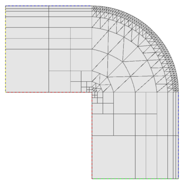
Visualizing the mesh
The following code illustrates how to visualize the mesh using the MeshView class:
// Display the mesh.
// (0, 0) is the upper left corner position
// 350 x 350 is the window size
MeshView mview("Hello world!", new WinGeom(0, 0, 350, 350));
mview.show(&mesh);
The class MeshView provides a method show() that displays a window with the mesh:
To see the graphical output, the main.cpp file should be finished with:
  // Wait for the view to be closed.
  View::wait();
  return 0;
}